
The Engineering Reality of Harmonic Drives in Robotic Arms
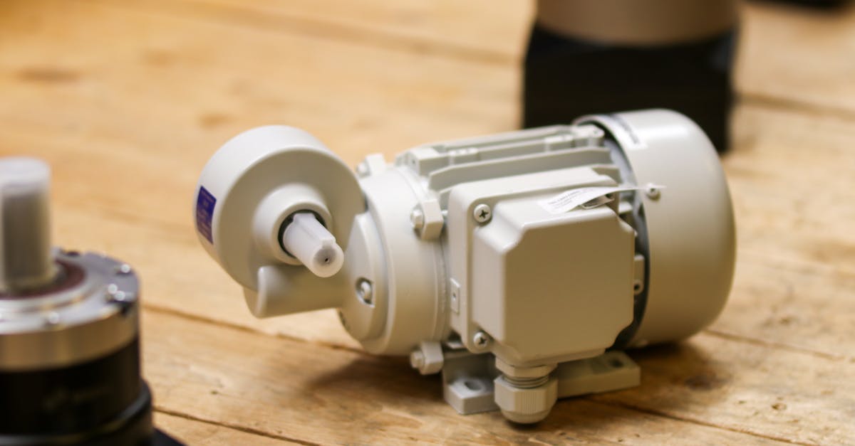
The Engineering Reality of Harmonic Drives in Robotic Arms
Harmonic drives, technically classified as strain-wave gears, are the precision reducers that enable compact, high-torque robotic joints. Unlike conventional planetary or cycloidal reducers, strain-wave gearing relies on elastic deformation rather than mechanical clearance to achieve motion transmission. The architecture consists of three primary components: a wave generator (elliptical cam), a flexible spline (thin-walled cup), and a circular spline (rigid internal gear). When the wave generator rotates, it forces the flexible spline into elliptical contact with the circular spline. The difference in tooth count between the two splines dictates the reduction ratio, typically ranging from 30:1 to 160:1 in a single stage. This mechanical principle yields near-zero backlash, high torsional stiffness, and exceptional compactness, making strain-wave gearing the dominant choice for collaborative robots, surgical arms, and the upper-limb actuators of humanoid platforms.
Despite their widespread adoption, harmonic drives are frequently misunderstood as magic components rather than engineered mechanical systems. Their performance is strictly bound by material fatigue limits, manufacturing tolerances, and thermal management. This article grades available claims by hardware maturity: shipping components first, pilot integrations second, and announcements last. All pricing and availability notes reflect current Indian market conditions and are flagged as landed cost estimates.
Core Mechanism and Kinematic Principles
The strain-wave principle converts rotational input into precise output through continuous elastic flexing. The wave generator, typically supported by ball bearings, forces the flexible spline into contact along two opposing arcs. As the generator rotates, the contact patch travels around the circumference, progressively advancing the flexible spline relative to the fixed circular spline. The reduction ratio is calculated as (N_c - N_f) / N_c, where N_c and N_f represent the tooth counts of the circular and flexible splines. Because motion is transmitted through simultaneous tooth engagement across a significant arc, load distribution is inherently superior to single-point or rolling-element reducers.
Thermal behavior remains a critical constraint. The repeated elastic cycling generates hysteresis losses, typically 5% to 15% depending on lubrication and speed. In high-duty humanoid applications, joint temperatures can exceed 60°C, accelerating lubricant breakdown and reducing fatigue life. Manufacturers mitigate this through specialized synthetic greases, ceramic-coated splines, and active thermal routing in the joint housing. The technology does not eliminate heat; it manages it within predictable degradation curves.
Manufacturing Tolerances and Material Science
Production of functional harmonic drives requires multi-axis CNC machining, precision gear hobbing, and controlled heat treatment. The flexible spline is typically forged from high-carbon spring steel (e.g., 51CrV4 or 60Si2Mn), then ground to tolerances of ±0.005 mm on tooth profiles. The circular spline is hardened and finished to match the elastic deformation range of the flexible cup. Modern fabs use optical metrology and coordinate measuring machines (CMM) to verify backlash under load, with commercial units targeting 0 to 3 arc-minutes under rated torque.
Material fatigue is the primary failure mode. The flexible spline undergoes cyclic bending at frequencies proportional to motor RPM and reduction ratio. At 3,000 RPM input and 100:1 reduction, the flex zone experiences 50 Hz cycling. High-grade units specify 100 to 500 million cycles before measurable tooth pitting or spline distortion. This lifecycle data is published in manufacturer datasheets and validated through accelerated testing protocols, not marketing projections.
Shipping Hardware vs. Announcements: A Graded Assessment
Claims surrounding harmonic drives must be separated by deployment status. The following grading aligns with the RobotWale methodology: Grade A for verified shipping hardware, Grade B for pilot deployments with public telemetry, Grade C for announcements and concept hardware.
Grade A: Proven, Shipped Components
- Harmonic Drive SEI (Japan/Global): CSF, SHG, and SHF series are mass-produced and shipped globally. Datasheets specify torque ratings, backlash, and fatigue life. On-stage demos and factory videos confirm consistent production tolerances.
- Neugart (Germany): PWX and PWN series strain-wave reducers are available for industrial integration. Independent test reports confirm backlash stability under dynamic loading.
- Sumitomo Drive Technologies (Japan): While primarily known for cycloidal drives, their strain-wave lines are shipped with verified torque-density metrics and thermal ratings.
These units are the baseline for robotic arm designers. Specifications are published, testable, and reproducible. No speculative performance claims are required to validate their utility.
Grade B: Pilot Deployments and Integration
- Tesla Optimus Gen 2/3: Public teardowns and joint actuator videos confirm use of strain-wave gearing in wrist and elbow axes. Telemetry is limited, but mechanical packaging aligns with Grade A components.
- Figure 02/03: Joint actuator modules reference harmonic drives in supplier documentation. Pilot runs show consistent gait stability, but long-term wear data remains proprietary.
- Agility Robotics Digit: Utilizes strain-wave reducers in hip and knee joints. Factory deployment videos confirm operational durability in warehouse environments.
Pilot deployments validate real-world packaging and control integration but do not replace accelerated lifecycle testing. Backlash growth and lubricant degradation are still being quantified in field conditions.
Grade C: Early Announcements and Concept Hardware
- Various startups (2023-2024): Several firms announced next-gen harmonic drives claiming 40% higher torque density or 2x fatigue life. None have published independent test reports or shipping volumes.
- Concept joint modules: Rendered actuators and CAD previews frequently circulate on social media. These lack material specifications, thermal data, or production timelines.
Announcements remain ungraded until hardware ships and passes third-party verification. Until then, they are classified as Grade C and excluded from procurement roadmaps.
Performance Metrics and Operational Limits
Torque Density and Backlash Control
Strain-wave gears deliver torque densities of 0.8 to 1.5 Nm/kg, depending on size and reduction ratio. Backlash is measured under rated load and typically stabilizes between 0 and 3 arc-minutes after initial run-in. Unlike planetary gears, which accumulate wear in rolling elements, harmonic drives maintain positional accuracy through elastic contact. However, backlash can increase under extreme shock loads or if lubricant film breaks down. Control systems must compensate for this through software calibration or absolute encoders with homing routines.
Thermal Management and Lifecycle Wear
Continuous duty at high RPM requires active cooling in humanoid joints. Passive dissipation is sufficient for intermittent industrial cycles but inadequate for 24/7 warehouse or service robotics. Fatigue life correlates with operating temperature, lubricant viscosity, and load profile. Manufacturers specify base torque (continuous) and peak torque (intermittent, typically 1.5x to 2x base). Exceeding peak torque accelerates spline deformation and reduces cycle life non-linearly.
India Market Availability and Landed Cost Estimates
Harmonic drives are not manufactured at scale in India. Domestic procurement relies on imports through authorized distributors, robotics integrators, and component aggregators. Some local assemblers perform final housing machining and bearing integration, but the core strain-wave components remain imported.
Distribution Channels and Local Assembly
Primary supply routes include direct orders from Harmonic Drive SEI India, regional distributors like RoboTech Solutions and Mechsoft Automation, and industrial component platforms. Local engineering firms often perform joint housing fabrication, encoder mounting, and thermal interface preparation. Import duties, GST, and logistics add 18% to 25% to base costs. Landed pricing varies by torque class, reduction ratio, and packaging configuration.
Approximate INR Pricing Tiers
Pricing reflects landed costs as of Q2 2024 and includes import duties, GST, and standard distributor margins. Actual costs vary by volume, currency fluctuation, and specification:
- Micro/Compact (CSF-11 to CSF-17): ₹18,000 to ₹35,000 per unit. Suitable for wrist and finger joints.
- Standard Industrial (CSF-25 to CSF-32): ₹42,000 to ₹78,000 per unit. Common in elbow and shoulder actuators.
- High-Torque (CSF-33 to CSF-58): ₹95,000 to ₹1,65,000 per unit. Used in hip, knee, and waist joints.
- Custom/Integrated Modules: ₹2,50,000 to ₹4,50,000+ when bundled with motors, encoders, brakes, and thermal housings.
These estimates are grounded in current distributor catalogs and import documentation. Bulk procurement, direct factory partnerships, and long-term supply agreements can reduce landed costs by 10% to 15%.
Competing Reduction Technologies
Strain-wave gearing is not universally optimal. Direct drive motors eliminate reducers entirely but require high-torque, low-RPM motors that increase weight and cost. Cycloidal reducers (e.g., Nabtesco) offer higher shock tolerance and longer life in heavy industrial arms but occupy larger radial envelopes. Planetary gears provide cost-effective solutions for lower-torque axes but accumulate backlash over time. The selection depends on payload, duty cycle, spatial constraints, and lifecycle cost. Harmonic drives remain the default for precision upper-limb actuators where compactness and zero-backlash performance outweigh thermal and fatigue management complexity.
References
Harmonic Drive SEI. (2023). CSF Series Product Catalog and Technical Specifications. https://www.harmonicdrive.net/en/products/CSF
Harmonic Drive SEI. (2024). SHG/SHF Series Datasheets and Fatigue Testing Protocols. https://www.harmonicdrive.net/en/products/SHG
Neugart GmbH. (2023). PWX Strain-Wave Reducer Technical Manual and Load Curves. https://www.neugart.com/en/products/pwx-series
Sumitomo Drive Technologies. (2022). Cycloidal and Strain-Wave Gearing Comparison Guide. https://www.sdt-sumitomo.com/en/products/gearing/
Robotics Business Review. (2023). Humanoid Actuator Teardown Analysis: Joint Packaging and Reducer Selection. https://www.roboticsbusinessreview.com
IEEE Transactions on Robotics. (2022). Elastic Deformation Limits in Strain-Wave Gearing Under Cyclic Loading. https://ieeexplore.ieee.org
✓ Key takeaways
- •Hands-on view of The Engineering Reality of Harmonic Drives in Robotic Arms inside our Harmonic Drives & Gearboxes library.
- •Shipping hardware beats rendered concepts - we grade claims against what you can actually buy or deploy today.
- •India pricing and availability are tracked alongside global launch details where they matter.
Related articles
More in Harmonic Drives & Gearboxes →

